In any belt-driven system, two major troubles can be belt slippage and excessive tension. Improper belt tension causes both. The motor mounting base usually sets how well you can control tension. Choose it wisely.EDWARD J. BEES, Vice President,
|
|
|
When you assure correct belt tension, the rewards are substantial: better drive efficiency, less downtime, and fewer maintenance requirements. And you extend the service life of the belt, motor bearings, and other system components. Ideal belt tension is "just enough" to drive the maximum anticipated load without slippage. Some people call it "proper tension" — the level at which you get maximum drive efficiency while imposing lowest possible stresses on the belt, bearings, and components of the driven member. Too much tension needlessly stresses these same components, leading to premature failure. Too little causes belt slippage, heat, loss of available power, and needless wear on belts and pulleys. Motor bases to set belt tension come in two broad categories:
What frequently happens in industry is that different parties become involved in design, fabrication, and installation of equipment. Someone, somewhere down the line, is faced with procuring a motor mounting base — often with little or no thought for the important implications of belt tension adjustment and control. So, that person orders a fixed-position base to fit the motor's mounting dimensions. And where the system application really calls for a tension-controlling base, you can predict trouble. Let's see what the different types of motor mounting bases will or won't do in providing greater system efficiency, lower maintenance, and longer system life. Fixed-position adjustable motor basesA fixed-position adjustable base lets the motor be pushed or pulled into position, so the belt can be installed and adjusted. After the belt is pulled over the pulley and before the mounting bolts are tightened, one or more adjusting screws force the motor away from the driven pulley until the desired tension is reached. |
|
|
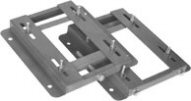
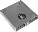
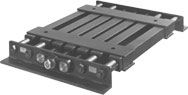
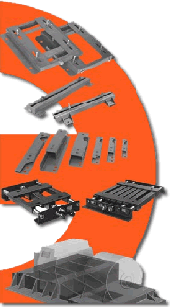
Base construction varies, from a one-piece formed plate to beefed-up versions that include Z-bars and continuous welding for greater strength. Sizes and styles are available to fit motors from fractional horsepower to over 200 hp and to mate with NEMA mounting dimensions. The single adjustable base has a central screw for tension positioning. As you turn the screw you move the motor (and its pulley's center) toward or away from the driven pulley's center. Because of this style's simplicity and economy, it offers a cost-effective solution for many applications. In general, single-screw styles can serve on motors from fhp to 150 hp. A dual positioning base such as the one in Figure 1 has two adjusting screws located directly under the motor feet. This style comes in configurations identical to single-adjustable bases, as well as in reinforced construction to extend the application range to about 200 hp. The major difference in the two styles is that dual screws provide a simple and positive way to hold alignment. As belt tension is applied, the motor drive end is pulled away from the driven unit. The mounting nuts are not tightened until tension adjustment is complete. The misaligned condition shown in Figure 1 should not occur if the screws are adjusted correctly. By alternating turns between the two screws, alignment is maintained at the same time tension is adjusted. With the single screw, you must pry and hold the motor in an aligned plane as the mounting bolts are tightened. Depending on motor size, the alignment tool can be as simple as a screwdriver or pry bar. To hold a larger motor in place you may need a hoist or Come-Along. Many standard fixed-position bases have mounting studs that protrude from slots. You must lift the motor over the studs during installation and loosen the nuts to make tension adjustments. A caution: Never loosen the mounting nuts more than absolutely necessary to let the motor be moved during tension adjustment. If they are too loose, the motor can pivot and lift toward the driven pulley during belt tightening. Then, when the nuts are tightened, belt tension will be higher than required and you may overstress the mounting studs. A special fixed-position adjustable base (see photos above) offers several advantages over standard models. It includes a mounting plate that moves as the adjustment screws are turned, to simplify installation, alignment, and tension adjustment. The movable plate not only makes it unnecessary to loosen and tighten bolts during adjustment, but also permits belt adjustment as the system runs. Fixed-position adjustable bases have applications from appliances and shop tools to industrial machines powered by motors weighing over 5,000 lb. In numbers, they are by far the most the motor be moved during common type. The big advantage is low initial cost; another, availability in standard styles for NEMA mounting dimensions. One manufacturer, for example, stocks over 225 styles and sizes. Selection considerations. Before settling on a fixed-position base, consider these major limitations:
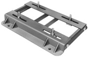
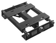
Tension-controlling basesWith the fixed adjustable base the chief limitation is that there is no way to adjust belt tension as load varies. The alternative is a base that can automatically adjust the center distance between pulleys as load requirements demand, while the system runs. Pivoting bases, Figure 2, use the motor's weight as well as its direction of rotation to apply and control tension. The motor mounts on pivoting arms. By locating the motor farther from the pivoting shaft, you increase belt tension; locating it closer, you decrease tension. Support arms, with bolt holes and slots sized to motor frames, let the motor be positioned and secured. During start-up, motor reaction torque moves the pivoted arm downward, thus increasing the pulley center distance and building up tension. As the operating load increases, the arms swing up, thus decreasing the center distance. Functionally, the pivoting base offers distinct advantages over fixed-position bases. However, because the motor must be positioned and adjusted to produce enough tension to drive full load, at less than full load this tension can be more than necessary. The pivot base principle also imposes restrictions. For example, the tight side of the belt must be between motor shaft and base pivot shaft; if not, reaction torque causes the base to rise and throw the belts off the pulleys. Usage is restricted to single-direction rotation and mounting is generally limited to horizontal positions. Spring-loaded bases, Figure 3, use a built-in spring or series of springs to control belt tension. The motor rides on cross members attached to tubes, making up a carriage that automatically moves toward or away from the driven member as load increases or decreases. The motor bolts to the carriage, which is free to move. Turning the adjustment screw clockwise causes the follower nut, spring, and carriage to move away from the driven pulley. After the belt is installed, further screw rotation moves the carriage until the belt is snug. Continued clockwise rotation causes the follower nut to compress the spring. The spring, in turn, exerts a force on the carriage, which results in tension being applied to the belt. The force exerted by the spring equals the total tension in the belt; both forces act upon the carriage in opposite directions, and the carriage is free to move to a neutral position where all forces balance — the free body is in equilibrium. Springs for spring-loaded bases are sized by the manufacturer. Adjustments are made on site as the mtor runs at the prevailing load. As load increases, belt tension increases until it exceeds the spring force. The spring then compresses and the carriage moves toward the driven pulley. As this happens, the increased spring force becomes equal to the increased belt tension. Whatever distance the carriage travels equals the additional distance the spring is compressed. Conversely, when belt tension decreases because the load lightens, the force of the relaxing spring moves the carriage away from the driven pulley. The result: tension is always maintained at a value just sufficient to keep the system operating at peak efficiency — with neither slippage nor excessive tension. A spring-loaded motor base makes for simple motor and belt installation: you make adjustments as the system runs; you need no calculations; and you do no guesswork in applying minimum tension to prevent slippage. The base can handle overload and shock without affecting system performance, and belt and bearing stresses are never excessively high. The emphasis in this article has been on belt tension control, because that is the key to higher system efficiency, lower maintenance, and longer life. In general, a fixed-position adjustable motor base can do that, though a more costly tension-controlling base might do better. Other aspects to consider include equipment location, environmental conditions, and unusual or special mounting requirements. Any of these could tilt the decision in favor of a tension-controlling base. A tension-controlling base means fewer trips to a remote or nearly inaccessible site, less time devoted to adjusting belts that stretch more because of high temperature, and the freedom to mount the motor vertically or horizontally on walls or ceilings. |
|